AGRICULTURE

Dynamic range, bias instability, angular and velocity random walk—all essential elements that vary in robustness, performance and flexibility across inertial measurement units (IMUs). As the integration of these critical systems continues to expand in applications on the ground, at sea and in the air, engineers and integrators are asked to define the technology’s limits.
For practicality, a majority of inertial system testing is done on the ground with road vehicles and through simulations. With an eye on more dynamic—and extreme—conditions, a team of engineers at Hexagon | NovAtel looked to the skies; specifically, at a subsonic jet.
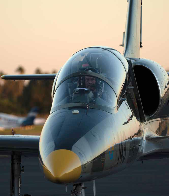
As a first-of-its-kind positioning, navigation and timing experiment for this group, the sensor fusion engineering team installed three commercially available IMUs on a civilian-owned Aero L-39 Albatros jet and put them through the rolls, dives and high-G turns not found in conventional testing routines. It’s a truth test that is expected to inform future development even as it provides some surprising results benefiting current applications.
The Aero L-39 Albatros jet is a two-seater, single engine high performance military aircraft with a max cruise speed of 750 kilometres per hour (466 miles per hour) and max acceleration of 5Gs.
The IMUs tested range across NovAtel’s IMU portfolio in terms of price and performance grades:
All three systems met acceleration and dynamic range requirements with 100-200 Hz output rates. Products with a all-in-one enclosure, like the PwrPak7D-E2 and CPT7, made mounting, power, configuration and data collection easier. With an eye on gathering as much data as possible, the team focused on raw GNSS radio frequency (RF) signals, the GNSS measurements, GNSS augmentation corrections through TerraStar Correction Services and the raw IMU sensor measurements.
The team also established a control including a base station on the ground that would allow high quality post-processed data of the truth trajectory through NovAtel’s Waypoint software.
As well, the team was able to get continuous absolute error estimates for position as well as position, attitude and velocity in 3D.
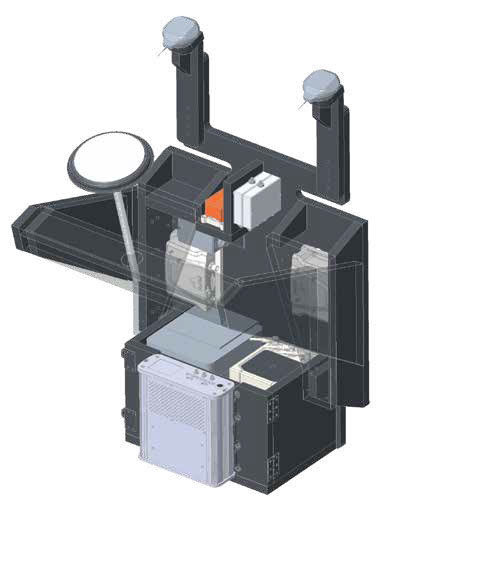
The IMUs were mounted in two separate installations: one set on a panel behind the pilot’s seat, and another on a seatform mount in the rear seat. The side-by-side mounting of multiple IMUs and sensors ensured that the engineering team could compare performance in general and identify when performance degraded or even stopped—which, it’s worth noting, didn’t happen during testing due to the resiliency of the products.
Three 60-minute flights were conducted with the pilot taking the aircraft through 5G turns, steep dives, aileron rolls and other demanding acrobatic aerial manoeuvres.
Once all of the flights were performed, the data was run through NovAtel’s Waypoint post-processing software to develop high quality truth trajectories.
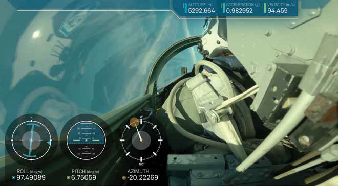
The goal from a data collection standpoint was two-fold. First, the team wanted to track real-time performance.
Second, they wanted to make sure there was sufficient data to post-process as more data allows for greater opportunities for manipulating variables and testing scenarios to drive system advancements. The RF signal recorder provides insight into the performance of different tracking algorithms on the signals present in the sky viewable by the antennas during the exercise, opening the door to a wider range of investigative analytics.
To cope with GNSS outages that can occur when the plane rolls in the air and blocks line-of-sight for the GNSS antenna, the team post-processed the data both forward and backward in time using NovAtel’s Waypoint Inertial Explorer software. As the data is processed, errors in the inertial solution accumulate over time due to these outages with an exponential upward growth. If the same processing procedure is conducted in reverse, starting at the end and moving to the beginning of the file, the forward and reverse solutions can be combined for a better quality trajectory.
“We meet in the middle of an outage,” said Sam Kiley-Kubik, geomatics designer with Hexagon | NovAtel, “and then take an average of the two runs to obtain a position velocity and attitude error that is much lower than it would have been in real-time or had we post-processed in just one direction.”
One of the biggest impressions from the extreme testing, noted the engineering team, was that each unit exceeded expectations across all three flights.
Bryan Leedham, product manager for enclosures and post-processing software at Hexagon | NovAtel, said, “The high-grade IMU performed outstanding, as expected. More satisfying was that the other two performed better than we expected, especially given the improvised setup with the mounted patch antennas [in the cockpit dashboard]. While they’re not performing as well as full survey grade antennas, [the lower grade systzms] did a remarkably good job under the conditions, particularly in the attitude measurements.”
He noted that the lower cost antennas showed quite strong results through the outage testing. “In several sections of the tests, we were running 200 [Hz] samples at up to 20 second [GNSS] outages and the [results] look really competitive next to the high grade CPT7,” Leedham continued.
The inertial sensors all functioned as expected with no signs of failure induced by dynamics, with the navigation algorithms also performing well. Further, Kiley-Kubik said the vibration environment was also very permissive. The one challenge clearly noted was that the location of the mass market dash antennas, which were installed a few inches from the ejection seats, had a direct effect on satellite visibility.
“All of the antennas did quite well during the tracking, though manoeuvres such as high banks, the loss in tracking is quite a bit more severe for the dash antennas and they took longer to recover,” said Kiley-Kubik.
The benefits of GNSS+INS versus GNSS-only were also clearly evident.
“[This environment] is one of the easiest ways to see the benefits of INS,” noted Kiley-Kubik. “In relatively permissive conditions, we had similar position performance. But going into periods of large dynamics, we can really see the benefit of having an inertial system to bridge through those outages.”
In highly dynamic conditions, the GNSS errors jumped to 20 metres (65 feet) or more, using a standalone GNSS accuracy level, particularly on the dash units, while the GNSS+INS was less than two metres (6.5 feet) throughout.
“You also gain a continuous attitude and velocity solution, which GNSS is not capable of providing in most installations,” he added.
In terms of positioning accuracy, the effect of high performance GNSS antennas and higher quality IMUs are visible, especially during manoeuvres. “The position is driven by the superior GNSS solution with a better antenna,” explains Kiley-Kubik. “The two dash units are doing well, but having a tougher time during the manoeuvres and recovering from the rolls.”
The same error scenarios are visible in the velocity domain. NovAtel’s PwrPak7D-E2 entry grade MEMs IMU in particular shows a slightly decreased level of performance: “That’s a factor of the sensor quality,” continued Kiley-Kubik
“One of the pleasant surprises was attitude accuracy, where all sensors were within 0.5 degrees, which is fantastic and usually more than enough for navigation,” added Kiley-Kubik. “The higher grade [IMUs] really stand out here from the entry-level.”
One of the huge advantages of the L-39 IMU testing will be the ability to review the data and impose GNSS outages of arbitrary duration to characterise error growth.
“This is an important analysis as it’s usually one of the best ways to characterise sensor performance and variability,” said Kiley-Kubik. “We can break out flight segments and check performance.”
As the jet rolled and turned over during its manoeuvres, the GNSS antennas were obstructed, creating error growth. Positioning accuracy during outages is determined by constraining that error growth. With SPAN technology’s deeply coupled GNSS+INS integration, the inertial navigation system can constrain the solution using individual or partial GNSS measurements, even if a full GNSS position is not available.
“We essentially do a data crop to evaluate performance improvements,” said Kiley-Kubik. “We can impose GNSS outages of arbitrary durations on top of the outages caused by dynamics. By enforcing that outage and measuring the growth, we can characterise the error growth. We can make firmware changes, run it again and see if we can improve it. Certain areas might include an examination of the beginning of the airplane rolling or the line of sight to the satellites as those satellites roll out of view.”
With that information and simulated GNSS outages on highly dynamic aerial data providing context, analysts have a better expectation of the error growth across conditions than if the test was limited to a ground vehicle trial. Further, these dynamic experiences help confirm whether the IMU’s performance is better or worse than expected in a dynamic scenario—in this case, the performance turned out to be better.
The L-39 experiment, while certainly exciting during the data gathering, has fueled the entire development team across departments at NovAtel to continue to innovate.
As shown in the Table 1, all three systems performed well.
Kiley-Kubik explained, “Even with the challenging install locations of the antennas, the sensors gave us a very reasonable performance. Even for low cost entry grade sensors hooked to the patch antennas, the error growth of 13 metres (43 feet) [after a 60 second GNSS outage] is still really good. Depending on the application, that result might be more than enough for position accuracy.”
This high-flying test data is important for continual future development, explains the testing team. That’s why it’s important to have multiple sensors with different layers of performance and why the team chose IMUs across the company’s portfolio in different price points and performance grades for the experiment.
“We can expose different receivers to the same tracking environment,” explained Leedham. “With the RF recorder, we have an opportunity to, for example, change our tracking algorithms and see how they react to get new measurements. There’s an opportunity for us to basically iterate on different tracking, positioning algorithms, inertial fusion algorithms and so on to see how a vehicle use case might behave.”
“This data gives us different benchmarks of a low, medium and high [IMU grades] so we can see how the algorithms perform with those different sensor qualities and we can zero in on each one of those grades and tweak and improve using this data set as a data point.”
With all data being added to NovAtel’s regression and continuous monitoring systems, product improvement developers can better simulate algorithm changes within the firmware. These developers can make changes, run the simulation before and after the change, and ultimately better understand the impacts and effects a potential change has on a specific use case for applications from drones to marine vehicles to rocket ejection seats.
One of the benefits of this testing, added Leedham, is that it showed we can push performance farther in some applications than previously thought. “Every customer has a different use case with different potential requirements. Certain applications require a very accurate attitude solution such as photogrammetry; small attitude errors translate to big position errors in these solutions. We have the data to understand the position errors of each grade of IMU in extreme conditions,” he said. This ultimately helps us determine the best piece of technology to suit the customer’s requirements.
But that’s just the beginning. Kiley-Kubik said, “In our post-processing tools, we’re kicking off outages starting every second and then averaging all the results so we can see [how the system performs] if the GNSS positioning disappeared completely.” Thanks to data from this real-life test, he explained, we can discover what other limits that the technology can push beyond in simulation. He concluded, “Bottom line, we can better differentiate IMUs in various performance conditions to meet customer needs, whether that’s better position, attitude, velocity or all three.”
Read the full PDF here: