AGRICULTURE
Autonomous applications, by definition, are designed to supersede human oversight. With no human to help determine if there is an error, it is vital sensor outputs used by sensor fusion in autonomous applications are reliable. Using an erroneous position solution, an AV may make decisions based on incorrect data, leading to potentially hazardous situations. Before sensor fusion can combine an output source with other data for positioning, it requires a guarantee of integrity. AVs can only be expected to be widely adopted when the underpinning technology can be proven to be consistently reliable.
How positioning data is validated is crucial to ensuring integrity. Standard deviation is the accuracy metric normally used for positioning, which measures how far each output value is from the mean and specifies the expected error level in the output value.
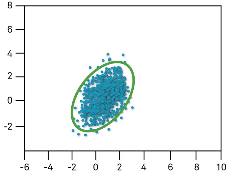
We can typically be more confident in positioning output datasets with a small standard deviation, where the positioning values are tightly clustered together and with relatively few outliers (Figure 55). When using a GNSS receiver to determine positioning, it is ideal to have many well-spread satellites available, as this helps provide greater accuracy. Latitude and longitude values for a fixed location, derived from healthy satellite geometry, will usually be centred when represented on a scatter plot and result in a small standard deviation.
Positioning is simply an estimation problem, and all measurements have errors, typically distributed in a centred or "Gaussian" (bell curve) manner. Standard deviation helps us quantify accuracy expectations from our positioning errors and determine when normal, or Gaussian, data value distributions are present. The use of standard deviation to assign a confidence ellipse helps define the likelihood of an actual position falling within a designated region a certain percentage of the time. For example, as portrayed in green in Figure 55, a 3-sigma confidence ellipse (3 standard deviations) means that we can expect the actual position to fall within this defined area 99.7% of the time.
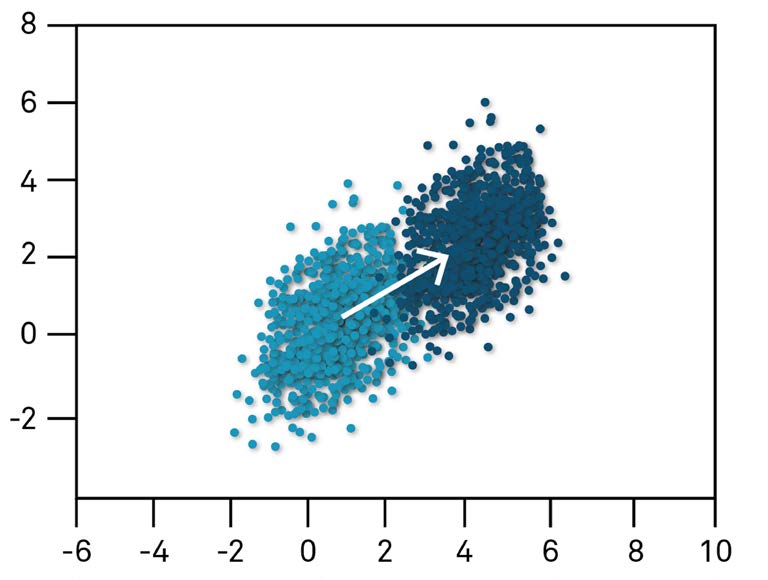
As standard deviation measures how far each output value is from the mean, you might think that simply widening the error ellipse would help to ensure integrity. Unfortunately, this breaks down when measurements are no longer Gaussian or have a systematic bias due to measurement faults. The standard deviation approach does not mitigate against positioning errors such as multipath (as discussed in Chapter 4), represented in Figure 56 by dark blue dots.
Beyond multipath, the GNSS receiver alone may encounter many other issues such as satellite orbit calculation error or ionospheric interference. However, in designing an AV positioning system, every potential failure point for every sensor needs to be considered for all possible operating conditions, which equates to billions of possible scenarios where a failure could occur. The use of a protection level supersedes the confidence ellipse for autonomous applications that require high integrity inputs.
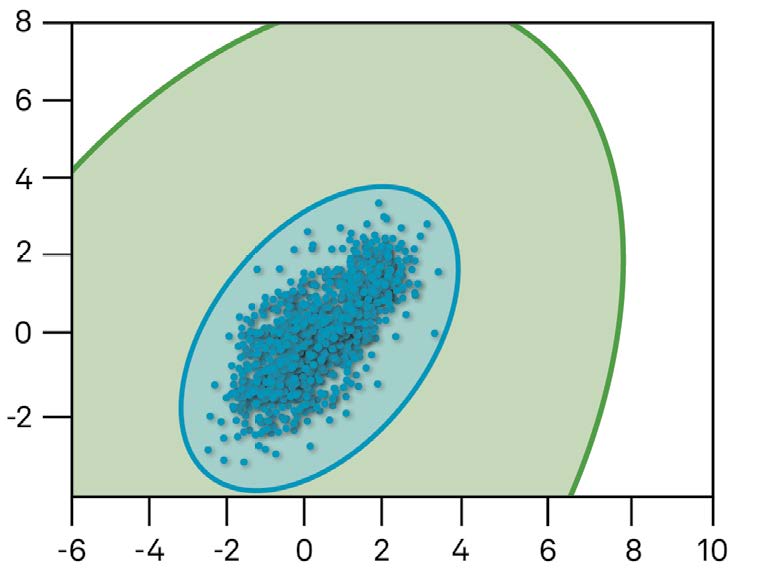
Protection levels provide a means to quantify and guarantee the maximum degree of error expected to exist by calculating a robust maximum error bound against erroneous input data. Looking at an example, suppose that our GNSS receiver has allowed us to determine a 3-sigma position error accurate to within 2 metres, corresponding to the blue sphere in Figure 57. The GNSS receiver may also separately provide us with a 99.9999% protection level of 8 metres (8.8 yards). The GNSS receiver has effectively calculated a 0.0001% chance that our actual position falls outside the 8 metres (8.8 yards) green zone of Figure 57.
Protection levels will grow and shrink dynamically to maintain the selected confidence level in response to different environments. A drop in satellite visibility introduced to our data in Figure 57 may result in the protection level increasing from 8 metres (8.8 yards) to 10 metres (10.9 yards) to maintain the 99.9999% confidence guarantee, as there is now a higher chance that the error could be greater than 8 metres (8.8 yards) but less than 10 metres (10.9 yards). The protection level may grow to a point where it exceeds a static reliability threshold known as an alert limit and is no longer considered safe.
Figure 58 shows a Stanford diagram, which provides a more precise means to visualise the relationship between positioning errors, protection levels and alert limits. Figure 57 provided an example of a protection level that grew in response to errors and remained greater than the positioning error. As the protection level tries to account for the worst possible undetected faults, protection levels will normally remain greater than positioning errors. Consequently, as a Stanford diagram plots position error against protection level, every position point in the diagram should fall within the normal operation zone, as shown in Figure 58.
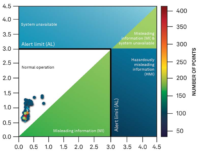
An alert limit of 3 metres (3.3 yards) is in place to ensure the use of the position only if the error is guaranteed to be less than 3 metres (3.3 yards). The alert limit would trigger in response to a protection level greater than 3 metres (3.3 yards), rejecting the position from use as it would no longer be considered safe. Misleading information occurs when position errors are greater than the protection level but below the alert limit. Such errors are not flagged as hazardous since the protection level remains less than the alert limit, but they are misleading since the error exceeds the protection level. It is crucial in safety- critical applications to avoid the worst-case scenario, where the position error exceeds the alert limit, but the protection level remains below the alert limit. This type of error would be hazardously misleading information since the protection level tells the user that the position is safe to use when the error exceeds the alert limit.
We have used the idea of the GNSS receiver calculating protection levels. In reality, a separate system may handle calculating protection levels for the GNSS receiver and other sensors in a process known as centralised or parallel processing. While perfect for helping visualise the surrounding environment, most AV cameras, for instance, may have insufficient processing power to determine protection levels. The use of dedicated equipment allows a place to run the advanced algorithms necessary to establish protection levels and perform the broader task of sensor fusion, tying together the various sensor inputs. Centralised processing also helps keep the design of an AV cost-effective and scalable in production while guaranteeing the protection levels necessary to aid reliable autonomous navigation.
Functional safety is the fine art of quantifying the extent of trust held in a system to perform safely in hazardous conditions and ensuring that mitigating actions are in place should an error occur. AV development must consider all possible errors and meet required automotive safety standards, such as ISO 26262 for on-road applications, from initial concept to final validation and testing. Addressing thousands of potential failure points, it may be no surprise that determining integrity throughout the entire development cycle can easily become a massive undertaking.
We have focused on how we can establish the absolute integrity of an AV without consideration for how the various underlying AV technologies communicate. Vehicles such as cars built with AV technology allow sensors to communicate via the internal data buses found on most modern automobiles. Acting like the nervous system of a vehicle, the communication bus provides a robust and reliable primary means for onboard sensors to communicate and aid navigation. However, AVs also incorporate increasingly externally connected technology, which leads to more significant potential for accidental user misuse of the system or an intentional malicious interception of a vehicle remotely. Vehicle safety may become compromised by a user interacting with the vehicle in an unanticipated manner or an attacker exploiting any number of available attack vectors. The ISO 21434 Road vehicles — Cybersecurity engineering standard provides a guideline to manage potential cybersecurity threats during the development process.
When it comes to building a safe and more secure AV system, from initial concept to product delivery, well-defined processes must be in place to meet stringent safety and security standards. The most effective approaches consider both functional safety and cybersecurity considerations efficiently and holistically. One such approach during the development lifecycle is to merge both the functional safety and cybersecurity analysis streams. Figure 59 shows an overview of both functional safety and cybersecurity analysis streams. Separately they are sufficient to meet the requirements set out in ISO 26262 and ISO 21434; however, a more effective development lifecycle is possible when executed in parallel, with avenues for integration implemented.
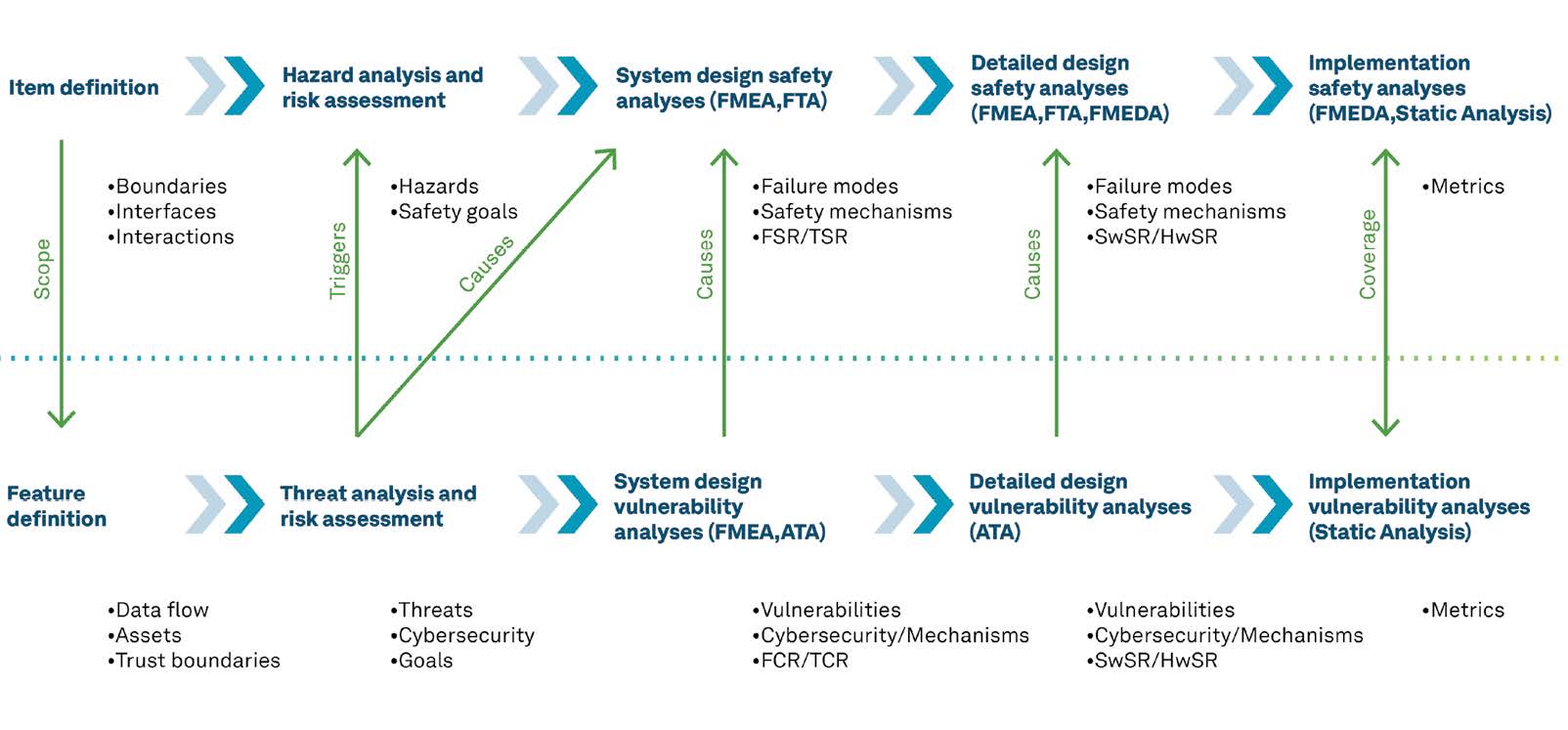
Upon closer inspection, we can see that the initial functional safety analysis activity is Item Definition, which details boundaries, interfaces and interactions. Once complete, this activity is available as an input to the initial cybersecurity Feature Definition step, which defines the flow of data, the assets and the trust levels between different elements and informs the cybersecurity Threat Analysis and Risk Assessment activity. This step can provide vital considerations to the functional safety Hazard Analysis and Risk Assessment activity, as any compromised component could potentially cause malfunctioning behaviour in multiple other system components or software. These initial steps provide a means to formulate safety goals that the rest of the development cycle must fulfil to determine failure modes, safety mechanisms and the metrics for testing functional safety and cybersecurity requirements.