AGRICULTURE
As discussed, GNSS uses signals from orbiting satellites to compute position, time and velocity. GNSS navigation has excellent accuracy, provided the antenna has line of sight to at least four satellites. When the line of sight to satellites is blocked by obstructions such as trees or buildings, navigation becomes unreliable or impossible.
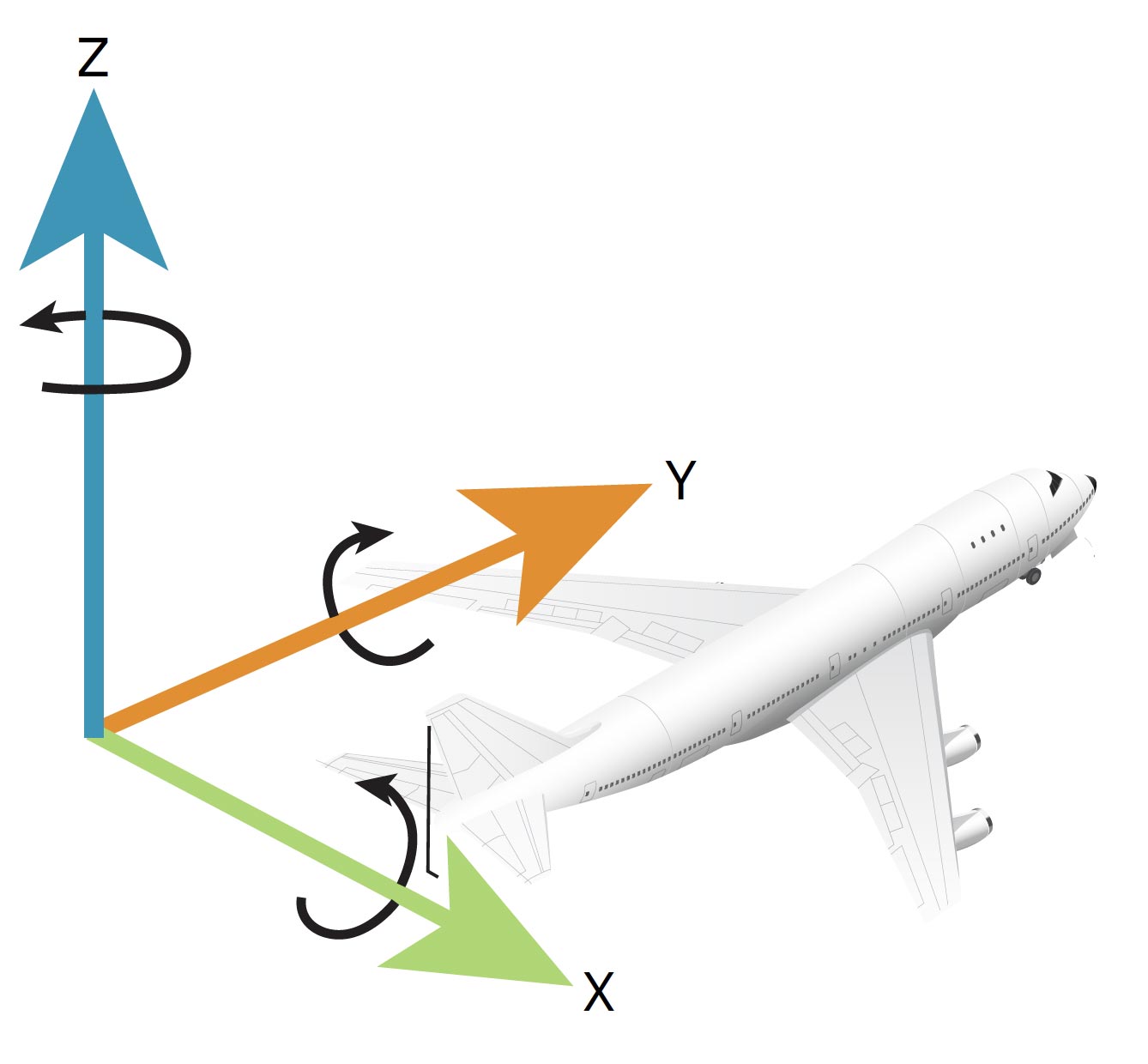
An INS uses angular rate and acceleration information from an Inertial Measurement Unit (IMU) to compute a relative position over time. An IMU is made up of six complementary sensors arrayed on three orthogonal axes. On each of the three axes, an accelerometer and a gyroscope are coupled. The accelerometers measure linear acceleration, and the gyroscopes measure rotational rates. With these sensors, an IMU can measure its precise relative movement in 3D space. The INS uses these measurements to calculate position and velocity. An additional advantage of the IMU measurements is they provide an angular solution about the three axes. The INS translates this angular solution into a local attitude (roll, pitch and azimuth) solution, which it can provide in addition to the position and velocity.
The ability of the INS to provide attitude determination is an important addition for several applications, such as aerial survey, hydrography and autonomous vehicles. For example, in an autonomous vehicle, it is not only important to know where the vehicle is and how fast it is travelling, but also the direction in which the vehicle is headed.
An IMU provides the accelerations and rotations to the INS system as discrete measurements at a specific frequency. Typically, INS systems run at rates between 50 and 1,000 Hz, although most IMUs are capable of sampling their data at much faster rates.
Of course, all systems, including IMUs and therefore INS, have their own drawbacks. First, an INS provides only a relative solution from an initial starting point. This initial start point must be provided to the INS. Second, and more critically, the high-frequency measurements provided by the IMU include several error sources. Depending on the quality (i.e., cost, size) of the IMU, these errors can be fairly large relative to the actual measurements being recorded. Navigating in 3D space with an IMU is effectively a summation (or integration) of hundreds to thousands of samples per second, during which time the errors are also being accumulated. This means that an uncorrected INS will drift from the true position quickly without a way to constrain the error growth. Providing an external reference to the INS, such as a GNSS-derived position, allows it to estimate the errors in the IMU measurements using a mathematical filter and mitigate their effect.
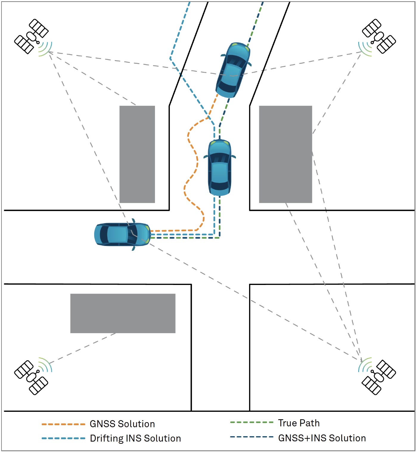
That external reference can quite effectively be provided by GNSS. GNSS provides an absolute set of coordinates that can be used as the initial start point. GNSS provides continuous positions and velocities, which are used to update the INS filter estimates. When GNSS is compromised due to signal obstructions, the INS system can continue to provide effective navigation for longer periods of time.
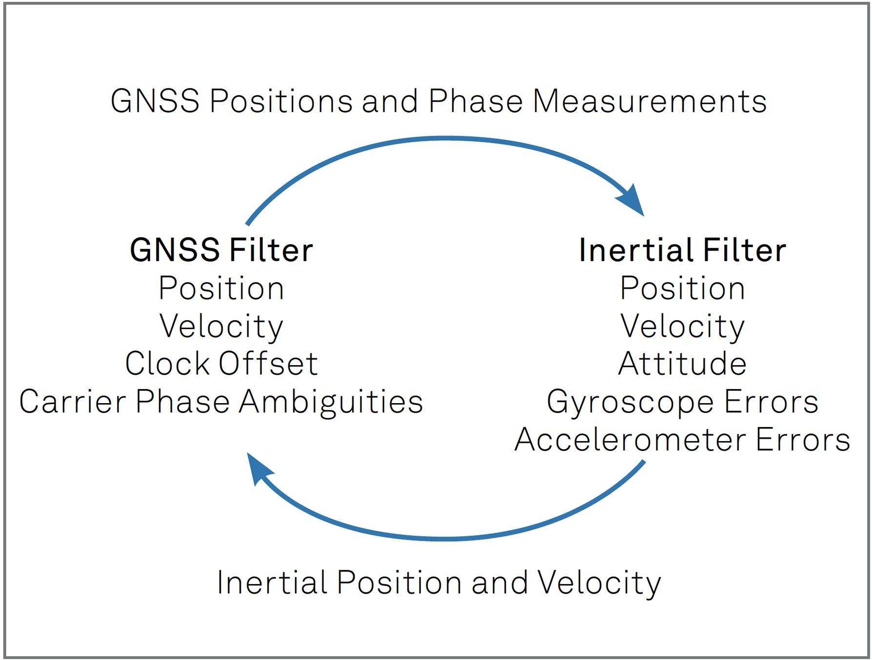
Using GNSS positions and velocities to estimate INS errors is called a "loosely coupled" system. However, GNSS+INS combined systems can get much more elaborate than that. A variety of terms such as "tightly coupled" or "deeply coupled" clearly indicate a much more symbiotic relationship between the two. In these systems, raw GNSS measurements are used directly to aid the INS, and the INS can even be used as a constraint to help GNSS reacquire lost signals more quickly or reject bad signals. Figure 49 shows a simplified diagram of a tightly coupled system.
Thus, when GNSS and INS are combined, the two techniques enhance each other to provide a powerful navigation solution, as illustrated in Figure 50. When the GNSS conditions are good (line of sight to several satellites), the GNSS receiver provides accurate position and time to the navigation system. When the GNSS conditions become poor, the INS provides the position and navigation until the GNSS conditions improve.